14 December 2021: Clinical Research
Finite Element Analysis of Horizontal Screw-Screw Crosslink Used in C1–C2 Pedicle Screw-Rod Fixation
Beiping Ouyang123AB, Xiaobao Zou12BC, Chunshan Luo3DE, Tingsheng Lu3E, Hong Xia2FG, Xiangyang Ma12A*DOI: 10.12659/MSM.932026
Med Sci Monit 2021; 27:e932026
Abstract
BACKGROUND: In the craniocervical junction, a C1-C2 pedicle screw-rod (PSR) fixation is applied to provide stability. The horizontal rod-rod crosslink (hR-R CL) is often used to enhance segmental posterior instrumentation. However, the biomechanics of the alternative horizontal screw-screw crosslink (hS-S CL) in the craniocervical junction are unclear.
MATERIAL AND METHODS: A nonlinear atlantoaxial instability 3-dimensional C1-C2 finite element model was constructed using computed tomography images. On this basis, 2 fixation models were established with C1-C2 PSR fixation using (1) a rod-rod crosslink (R-R CL), and (2) a screw-screw crosslink (S-S CL). Range of motion (ROM) of the atlantoaxial joint, stress distribution of the implants, and maximum stress value of the vertebral bodies were calculated and compared under 4 loading conditions, including flexion, extension, lateral bending, and axial rotation.
RESULTS: Atlantoaxial joint ROM was reduced by 90.19% to 98.5% with the hR-R CL, and by 90.1% to 98.7% with the hS-S CL, compared with the instability model. During axial rotation, the total stress peak of the PSR fixation was smaller with hS-S CL than with hR-R CL. The peak stress values of the vertebral bodies were comparable between the 2 fixation models.
CONCLUSIONS: The 2 tested crosslink models provided comparable stability. However, during axial rotation, the total stress peak of hS-S CL fixation was smaller than that of hR-R CL fixation. Since the atlantoaxial joint primarily functions as a rotational joint, our results suggested that the use of hS-S CL can provide a more stable environment for the implants.
Keywords: Atlanto-Axial Fusion, Biomechanical Phenomena, Finite Element Analysis, Internal Fixators, Atlanto-Axial Joint, Cervical Vertebrae, Humans, Imaging, Three-Dimensional, Male, Models, Anatomic, Pedicle Screws, Range of Motion, Articular, Tomography, X-Ray Computed
Background
Atlas (C1)-axis (C2) pedicle screw-rod (PSR) fixation has often been regarded as the criterion standard for treating atlantoaxial dislocation [1–3]. The atlantoaxial joint is responsible for over 50% of the axial rotation of the occipitocervical junction [4]. The internal fixation material must be able to restrict joint movement in all rotational axes to provide a strong fixed force. A transverse connector can enhance the rotational stability of the internal fixation [5], and the horizontal rod-rod crosslink (hR-R CL) is most commonly used in C1–C2 PSR fixation. However, intraoperative installation of the hR-R CL is difficult, resulting in prolonged operative time and even the possibility of spinal cord injury. The hR-R CL also impedes bone grafting. Therefore, an alternative transverse connector was designed to be on the screwhead, forming a horizontal screw-screw crosslink (hS-S CL), which is simple to place and firmly secure [6]. However, the difference between its biomechanical properties and those of the hR-R CL remains unclear. This paper aims to analyze and discuss the biomechanical characteristics of both types of cross-links by constructing a finite element model of a C1–C2 PSR fixation using hR-R and hS-S cross-links. By comparing the 3-dimensional finite element analysis of 2 different transverse connection installation methods, this study provides a theoretical basis for determining a suitable installation method in clinical practice.
Material and Methods
PARTICIPANTS:
We recruited a healthy male volunteer (age 30, weight 70 kg, height 172 cm) who had no history of cervical spine fractures, infections, or tumors or other lesions. This study was approved by the institutional Ethics Committee of the research institution.
STUDY DESIGN:
This current investigation is a case study.
CONSTRUCTION AND VALIDATION OF FINITE ELEMENT MODEL OF NORMAL ATLANTOAXIAL VERTEBRA:
The vertebral geometry data for the bottom of the occipital bone (C) to axis (C0–C2) were obtained from computed tomography scans with 1-mm section thickness (Siemens, Germany). The scanned images were saved in standard Dicom format. We input the Dicom data into Mimics (Materialise, Leuven, Belgium) and created a 3-dimensional spine model consisting of the occipital-atlanto-axial complex. Then, we used 3-matic software (Materialise) to obtain a finite element mesh for the spine model and simulated surgical procedures on it using Abaqus software (Dassault System, Paris, France). The resulting spine model contained the following major components: the lower part of C0, C1, C2, intervertebral cartilage, and 8 spinal ligaments. The spinal ligaments included the anterior longitudinal, posterior longitudinal, interspinous, flavum, alar, supraspinous, capsular, and transverse ligaments. The vertebral bodies were made of tetrahedral elements. The spinal ligaments were modeled using spring elements. Linear elasticity was applied to bone, intervertebral disc, and cartilaginous structures. The material parameters and the type of elements for each part are summarized in Table 1 [7,8].
To validate our model, we compared the range of motion (ROM) of the C0–C1 and C1–C2 segments of the intact finite element model with the results of the cadaveric experiment conducted by Panjabi et al [9] and the upper cervical finite element analyses conducted by Lapsiwala et al [10] and Zhang et al [11]. The ROM of the atlantoaxial segments was calculated based on nodal displacement [9]. Our results showed good agreement with each of the aforementioned studies, as presented in Table 2.
UNSTABLE FINITE ELEMENT MODEL OF THE UPPER CERVICAL SPINE:
We simulated the unstable atlantoaxial model by removing the ligaments from the intact C1–C2 model [12]. Internal fixators (modeling data provided by Weigao Orthopedic Materials Co Ltd, Shandong, China) were then implanted into the unstable model with each of the 2 crosslink techniques, as shown in Figure 1: once with C1–C2 hR-R CL, and once with C1–C2 hR-R CL.
BOUNDARY AND LOADING CONDITIONS:
The interactions among the vertebral bodies, cartilage, screws, and rods were defined as binding constraints. The lower surface of the axis was completely fixed in all directions. A reference point was created on the upper surface of the occipital bone and coupled with all the nodes on the top of the occipital bone. A 1.5-Nm moment [13] was applied on the reference point about the appropriate anatomic axes to induce flexion, extension, left and right-lateral bending, and left and right-axial rotation of the atlantoaxial joint.
Results
THREE-DIMENSIONAL ANGULAR ROM OF THE CONSTRUCTS:
Under a load of 1.5Nm, the ROM of each model in flexion, extension, lateral bending, and rotational directions was measured (Table 3). The ROM of the atlantoaxial instability model increased by at least 90%, compared with that of the unaltered, cervical fixation models, in all measured directions. The 2 models using the C1–C2 PSR fixations (hR-R and hS-S models) showed less than 10% difference in ROM, regardless of the fixation technique used. The 2 models showed a difference of 0.03º in flexion, 0.04º in extension, 0.02º in both left and right-lateral bending, and 0.01º in both left and right-axial rotation. Compared with the atlantoaxial instability model, the hR-R model reduced the ROM by 90.1% to 98.5% in all tested movement directions, whereas the hS-S models reduced the ROM by 90.1% to 98.7%, with the highest reduction in the left and right rotational directions.
STRESS DISTRIBUTION ON THE IMPLANTS:
The von Mises stress contour plot (Figures 2–4) showed that the stress distribution areas of each fixation technique were comparable. The stress peak of the hS-S CL was highest during flexion (301.19 MPa), while the hR-R CL had the maximum stress during left-axial rotation (379.8 MPa). Moreover, during axial rotation, the total stress peak of the hS-S CL model was smaller than that of the hR-R CL model (Figure 5).
COMPARISON OF MAXIMUM STRESS ON VERTEBRAL BODIES:
The maximum stress on the vertebral bodies was concentrated on the connection points between the screw and the bone. Both the hS-S CL model and the hR-R CL model had the highest peak stress during flexion and lowest peak stress during extension (Figure 6).
Discussion
Posterior atlantoaxial fixation and fusion is a commonly used surgical procedure for atlantoaxial dislocation, and stability of the fixation determines the curative effect of the surgery [14]. The screw-rod system has been widely used in clinical practice. Stability of the internal fixation is critical for bony fusion and, consequently, for a good clinical outcome [15,16]. Previous studies have shown that the application of a transverse connection can increase the stability of an atlantoaxial screw-rod internal fixation and have suggested that a transverse connection can make the bilaterally separated screw-rod structure into a singular unit, thus dispersing the stress concentration and improving the stability of the internal fixation [17,18]. Some scholars have reported that the use of a transverse connection in the spinal internal fixation system is still controversial [19,20]. Despite its biomechanical benefits, the transverse connection requires adding an implant to the screw-rod system and increasing surgical exposure, surgical time, and financial burden [19,20]. However, it has been generally agreed that a transverse connection can provide rotational stability for the atlantoaxial joint [21,22]. Owing to the difficulties associated with installation of hR-R CL, the risk of spinal cord injury and operative time increase during the procedure, leading to an increased risk of surgical infection. Additionally, the use of hR-R CL limits the space available for bone grafting.
Mizutani et al [6] first proposed the clinical application of on-the-screwhead crosslink connectors in the Goel/Harms procedure. Their study pointed out that this technique can achieve earlier bony fusion, and that, not only was this crosslink easy to install even after completing bone grafting, bone grafting was still conveniently performed after placing the crosslink. This crosslink technique, referred to as hS-S CL in the present study, overcomes the deficiencies of the traditional horizontal connection in clinical use. However, the biomechanical stability of this crosslink technique has not been studied. With this in mind, we utilized the finite element method to evaluate the biomechanics of hS-S CL to provide evidence for the value of this clinical application.
It can be seen from our results that PSR with hR-R CL fixation effectively reduced the ROM of the atlantoaxial joint, which was consistent with previous results [14–16]. We also found that PSR with the hS-S CL provided comparable stability to the hR-R CL in atlantoaxial fixation. The ROM of both of the fixation models decreased the most in axial rotation. It can also be seen from the von Mises stress contour plot that the transverse connection showed significant stress in axial rotation, indicating that the transverse connection provided anti-rotation stability, which is particularly important for patients with atlantoaxial rotation dislocation.
Stress distribution on the implants is closely related to the long-term stability of fixation techniques. The von Mises stress contour plot showed that the stress was mostly concentrated on the posterior part of the screw where it contacts the bone. When compared with the hR-R CL fixation, the hS-S CL showed high stress peaks on implants in flexion, extension, right-lateral bending, and right-axial rotation. During axial rotation, the total stress peak of the hS-S CL model was smaller than that of the hR-R CL model. Because the primary function of the atlantoaxial joint is rotation, the use of hS-S CL can provide a more stable force environment for the implants. The peak stress on the vertebrae bodies generally appeared at the contact sites between the bone and screws. The vertebra body of hS-S CL model had high stress in extension, left-lateral bending, and right-axial rotation, and the vertebra body of hR-R CL model had high stress in flexion, right-lateral bending, and left-axial rotation. The overall stress of the vertebrae bodies of the 2 fixation models was similar, which suggests that both fixation methods provided similar control of vertebral movement. According to both previous studies and the present study’s biomechanical results, the clinical application of hS-S CL provides more advantages than hR-R CL.
The limitations of this experiment need to be considered while interpreting the results. First, there is a gap between using the finite element model of the upper cervical spine and using a live human participant. This model does not account for muscle and other soft tissues, which may have an impact on the experimental results. Further studies should aim to assess the compatibility between internal fixations and human biological tissues as well as how those tissues impact mobility and stress distribution, which cannot be achieved by the finite element method at present. Second, the finite element analysis obtained in this experiment was instantaneous biomechanical data, ignoring the fatigue characteristics of internal fixation. Fatigue tests and fracture tests of internal fixations warrant further study.
Conclusions
From the mechanical viewpoint, hS-S CL fixation combined with C1–C2 PSR provided the same stability as hR-R CL fixation; however, hS-S CL fixation provided a mechanical advantage in axial rotation. The hS-S CL can be more conducive to clinical applications and shows promising prospects for future implementation.
Figures
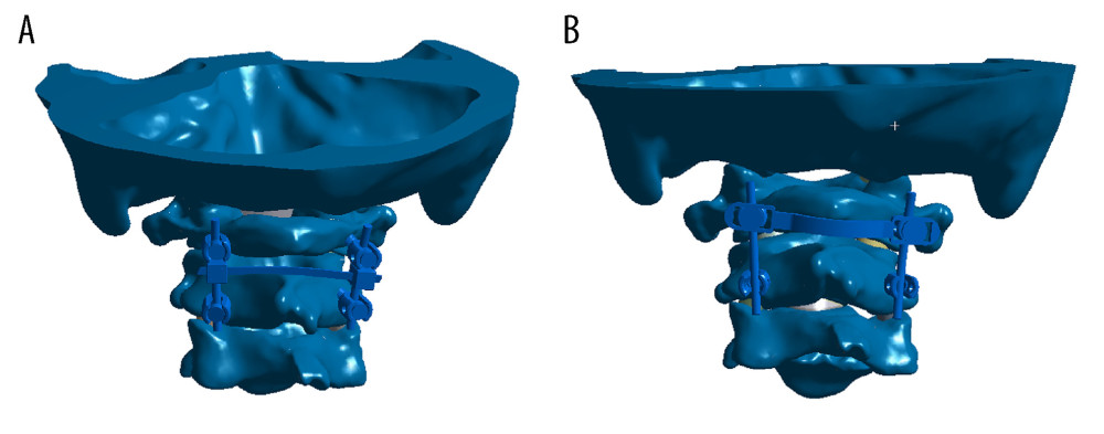 Figure 1. Two atlantoaxial fixation models: (A) horizontal rod-rod crosslink (hR-R CL) fixation model; (B) alternative horizontal screw-screw crosslink (hS-S CL) fixation model.
 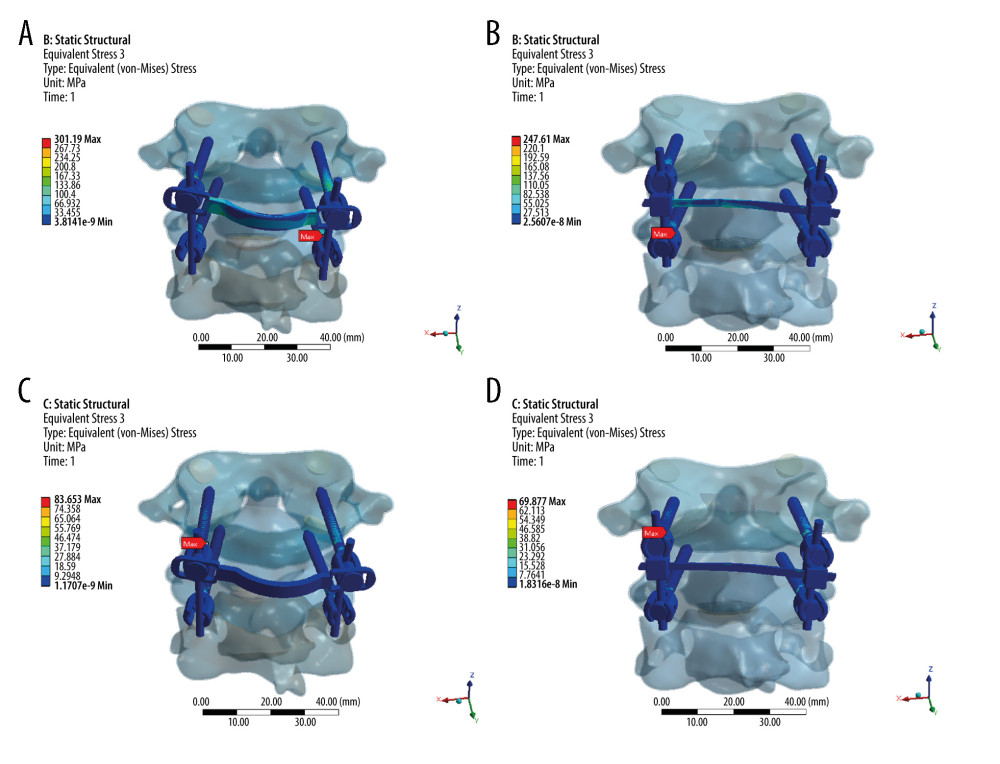 Figure 2. Stress distribution nephograms of implants for the 2 fixation models in flexion-extension: (A) horizontal screw-screw crosslink (hS-S CL) was tested in a flexion; (B) horizontal rod-rod crosslink (hR-R CL) was tested in flexion; (C) hS-S CL was tested in extension; and (D) hR-R CL was tested in extension after applying a 1.5-Nm moment.
 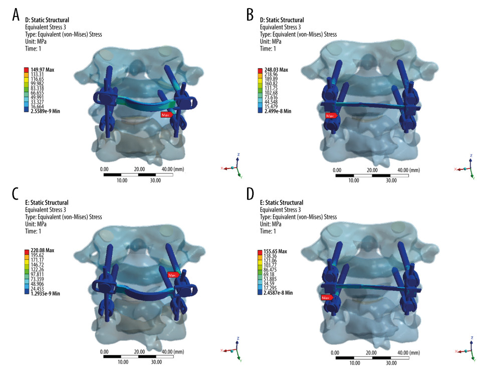 Figure 3. Stress distribution nephograms of implants for the 2 fixation models in lateral bending: (A) horizontal screw-screw crosslink (hS-S CL) was tested in left-lateral bending; (B) horizontal rod-rod crosslink (hR-R CL) was tested in left-lateral bending; (C) hS-S CL was tested in right-lateral bending; and (D) hR-R CL was tested in right-lateral bending after applying a 1.5-Nm moment.
 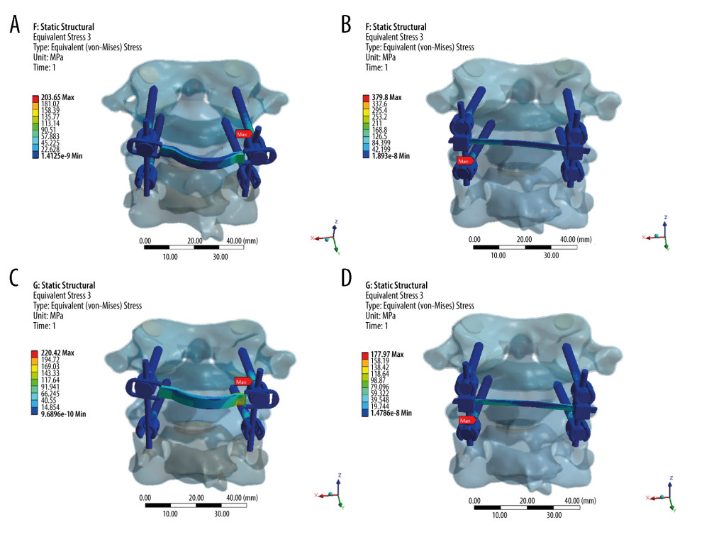 Figure 4. Stress distribution nephograms of implants for the 2 fixation models in axial rotation: (A) horizontal screw-screw crosslink (hS-S CL) was tested in left-axial rotation; (B) horizontal rod-rod crosslink (hR-R CL) was tested in left-axial rotation; (C) hS-S CL was tested in right-axial rotation; and (D) hR-R CL was tested in right-axial rotation after applying a 1.5-Nm moment.
 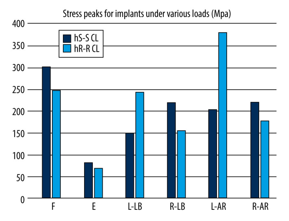 Figure 5. Comparison of stress peaks of implants.
 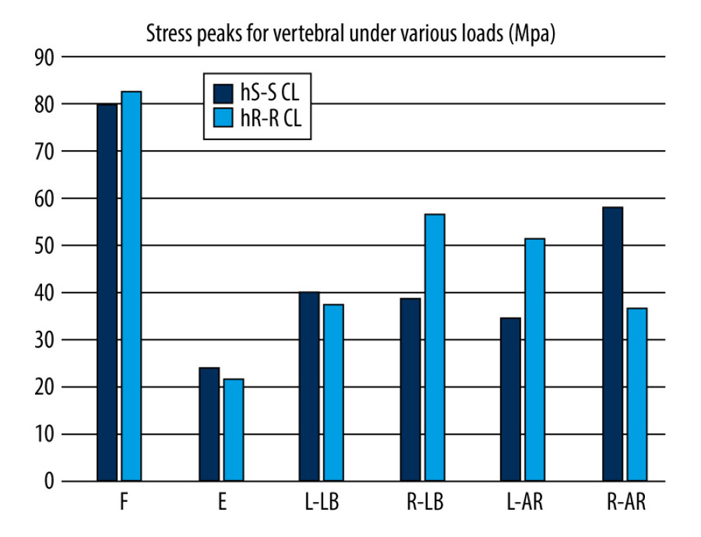 Figure 6. Comparison of stress peaks of vertebra.
 References
1. Yin Y, Tong H, Qiao G, Yu X, Posterior reduction of fixed atlantoaxial dislocation and basilar invagination by atlantoaxial facet joint release and fixation: A modified technique with 174 cases: Neurosurgery, 2016; 78; 391-400
2. Salunke P, Sahoo S, Khandelwal NK, Ghuman MS, Technique for direct posterior reduction in irreducible atlantoaxial dislocation: Multi-planar realignment of C1–2: Clin Neurol Neurosurg, 2015; 131; 47-53
3. Bhowmick DA, Benzel EC, Posterior atlantoaxial fixation with screw-rod constructs: Safety, advantages, and shortcomings: World Neurosurg, 2014; 81; 288-89
4. Yuan B, Zhou S, Chen X, Gallie technique versus atlantoaxial screw-rod constructs in the treatment of atlantoaxial sagittal instability: A retrospective study of 49 patients: J Orthop Surg Res, 2017; 12; 1-8
5. Cornaz F, Widmer J, Snedeker JG, Cross-links in posterior pedicle screw-rod instrumentation of the spine: A systematic review on mechanical, biomechanical, numerical and clinical studies: Eur Spine J, 2020; 30; 34-49
6. Mizutani J, Inada A, Kato K, Advantages of an on-the-screwhead crosslink connector for atlantoaxial fixation using the Goel/Harms technique: J Clin Neurosci, 2018; 50; 183-89
7. Ma X, Peng X, Xiang H, A finite element modeling of posterior atlantoaxial fixation and biomechanical analysis of C2 intralaminar screw fixation: Chin Med J (Engl), 2014; 127; 1266-71
8. Pitzen TR, Matthis D, Barbier DD, Initial stability of cervical spine fixation: Predictive value of a finite element model. Technical note: J Neurosurg, 2002; 97; 128-34
9. Panjabi MM, Dvorák J, Crisco J, Instability in injury of the alar ligament. A biomechanical model: Orthopade, 1991; 20; 112-20
10. Lapsiwala SB, Anderson PA, Oza A, Biomechanical comparison of four C1 to C2 rigid fixative techniques: anterior transarticular, posterior transarticular, C1 to C2 pedicle, and C1 to C2 intralaminar screws: Neurosurgery, 2006; 58; 516-21
11. Zhang H, Bai J, Nonlinear finite element analysis of C0-C1-C2 complex under physiologic loads: Conf Proc IEEE Eng Med Biol Soc, 2005; 6; 6165-67
12. Du JY, Aichmair A, Kueper J, Biomechanical analysis of screw constructs for atlantoaxial fixation in cadavers: A systematic review and meta-analysis: J Neurosurg Spine, 2015; 22; 151-61
13. Cai XH, Liu ZC, Yu Y, Evaluation of biomechanical properties of anterior atlantoaxial transarticular locking plate system using three-dimensional finite element analysis: Eur Spine J, 2013; 22; 2686-94
14. Chun DH, Yoon DH, Kim KN, Biomechanical comparison of four different atlantoaxial posterior fixation constructs in adults: A finite element study: Spine (Phila Pa 1976), 2018; 43; E891-97
15. Liu C, Kamara A, Yan Y, Biomechanical study of C1 posterior arch crossing screw and C2 lamina screw fixations for atlantoaxial joint instability: J Orthop Surg Res, 2020; 15; 156
16. Huang DG, Wang T, Hao DJ, Posterior C1–C2 screw-rod fixation and autograft fusion for the treatment of os odontoideum with C1–C2 instability: Clin Neurol Neurosurg, 2017; 163; 71-75
17. Brodke DS, Bachus KN, Mohr RA, Nguyen BK, Segmental pedicle screw fixation or cross-links in multilevel lumbar constructs. A biomechanical analysis: Spine J, 2001; 1; 373-79
18. Hart R, Hettwer W, Liu Q, Prem S, Mechanical stiffness of segmental versus nonsegmental pedicle screw constructs: The effect of cross-links: Spine (Phila Pa 1976), 2006; 31; E35-38
19. Scheer JK, Tang J, Eguizabal J, Optimal reconstruction technique after C-2 corpectomy and spondylectomy: A biomechanical analysis: J Neurosurg Spine, 2010; 12; 517-24
20. Shaw MN, Morel EP, Utter PA, Transverse connectors providing increased stability to the cervical spine rod-screw construct: An in vitro human cadaveric study: Lab invest J Neurosurg Spine, 2011; 14; 719-25
21. Papagelopoulos PJ, Currier BL, Neale PG, Biomechanical evaluation of posterior screw fixation in cadaveric cervical spines: Clin Orthop Relat Res, 2003; 411; 13-24
22. Brasiliense LBC, Lazaro BCR, Reyes PM, Stabilization of the atlantoaxial joint with C1–C3 lateral mass screw constructs: Biomechanical comparison with standard technique: Neurosurgery, 2010; 67; 422-28
Figures
 Figure 1. Two atlantoaxial fixation models: (A) horizontal rod-rod crosslink (hR-R CL) fixation model; (B) alternative horizontal screw-screw crosslink (hS-S CL) fixation model.
 Figure 2. Stress distribution nephograms of implants for the 2 fixation models in flexion-extension: (A) horizontal screw-screw crosslink (hS-S CL) was tested in a flexion; (B) horizontal rod-rod crosslink (hR-R CL) was tested in flexion; (C) hS-S CL was tested in extension; and (D) hR-R CL was tested in extension after applying a 1.5-Nm moment.
 Figure 3. Stress distribution nephograms of implants for the 2 fixation models in lateral bending: (A) horizontal screw-screw crosslink (hS-S CL) was tested in left-lateral bending; (B) horizontal rod-rod crosslink (hR-R CL) was tested in left-lateral bending; (C) hS-S CL was tested in right-lateral bending; and (D) hR-R CL was tested in right-lateral bending after applying a 1.5-Nm moment.
 Figure 4. Stress distribution nephograms of implants for the 2 fixation models in axial rotation: (A) horizontal screw-screw crosslink (hS-S CL) was tested in left-axial rotation; (B) horizontal rod-rod crosslink (hR-R CL) was tested in left-axial rotation; (C) hS-S CL was tested in right-axial rotation; and (D) hR-R CL was tested in right-axial rotation after applying a 1.5-Nm moment.
 Figure 5. Comparison of stress peaks of implants.
 Figure 6. Comparison of stress peaks of vertebra.
 Tables
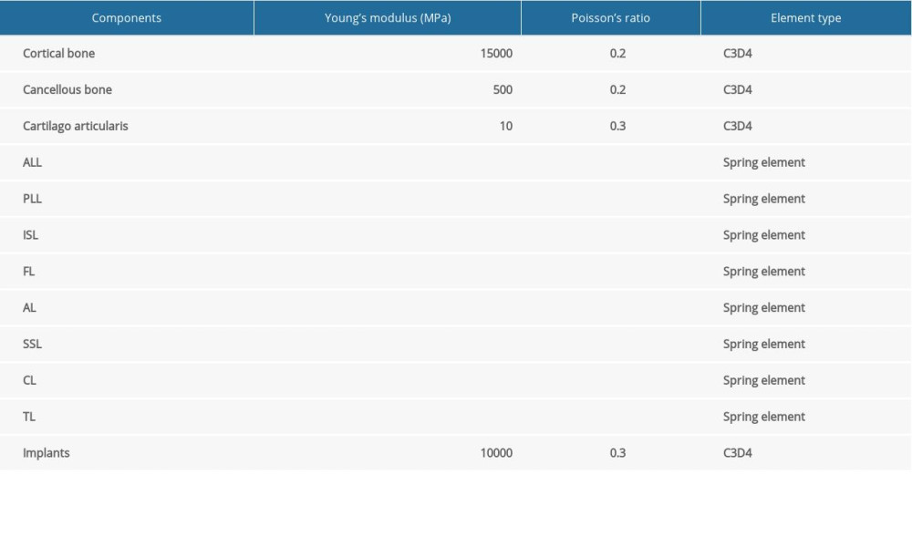 Table 1. Material property, designations, and element number of the finite element model.
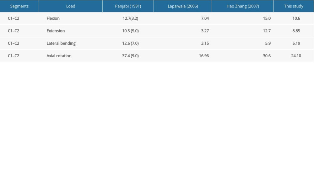 Table 2. Model validation.
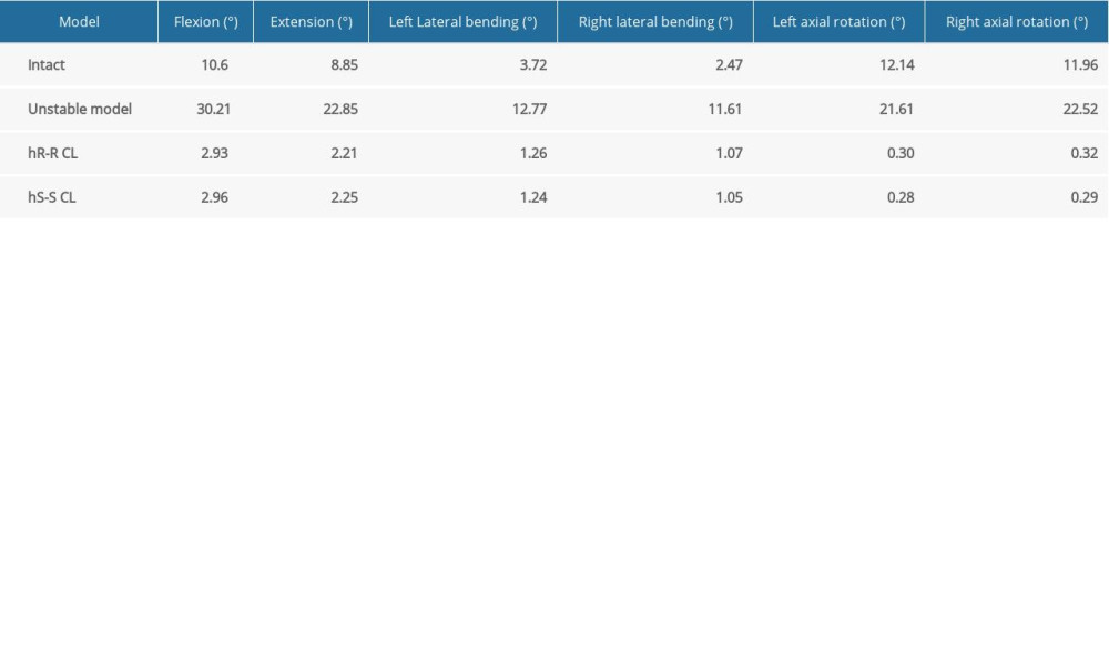 Table 3. C1–C2 range of motion of each group under different loading conditions.
 Table 1. Material property, designations, and element number of the finite element model.
 Table 2. Model validation.
 Table 3. C1–C2 range of motion of each group under different loading conditions.
 In Press
06 Mar 2024 : Clinical Research
Prevalence and Variation of Medical Comorbidities in Oral Surgery Patients: A Retrospective Study at Jazan ...Med Sci Monit In Press; DOI: 10.12659/MSM.943884
08 Mar 2024 : Clinical Research
Evaluation of Foot Structure in Preschool Children Based on Body MassMed Sci Monit In Press; DOI: 10.12659/MSM.943765
15 Apr 2024 : Laboratory Research
The Role of Copper-Induced M2 Macrophage Polarization in Protecting Cartilage Matrix in OsteoarthritisMed Sci Monit In Press; DOI: 10.12659/MSM.943738
07 Mar 2024 : Clinical Research
Knowledge of and Attitudes Toward Clinical Trials: A Questionnaire-Based Study of 179 Male Third- and Fourt...Med Sci Monit In Press; DOI: 10.12659/MSM.943468
Most Viewed Current Articles
17 Jan 2024 : Review article
Vaccination Guidelines for Pregnant Women: Addressing COVID-19 and the Omicron VariantDOI :10.12659/MSM.942799
Med Sci Monit 2024; 30:e942799
14 Dec 2022 : Clinical Research
Prevalence and Variability of Allergen-Specific Immunoglobulin E in Patients with Elevated Tryptase LevelsDOI :10.12659/MSM.937990
Med Sci Monit 2022; 28:e937990
16 May 2023 : Clinical Research
Electrophysiological Testing for an Auditory Processing Disorder and Reading Performance in 54 School Stude...DOI :10.12659/MSM.940387
Med Sci Monit 2023; 29:e940387
01 Jan 2022 : Editorial
Editorial: Current Status of Oral Antiviral Drug Treatments for SARS-CoV-2 Infection in Non-Hospitalized Pa...DOI :10.12659/MSM.935952
Med Sci Monit 2022; 28:e935952


