13 July 2020: Clinical Research
Structure Design and Optimization of the C5–C6 Cervical Intervertebral Fusion Cage Using the Anterior Cervical Plate and Cage Fixation System
Jiajia Wang12AE*, Zhihui Qian2BC, Changlei Cui3D, Zhijun Guo4F, Luquan Ren2GDOI: 10.12659/MSM.924236
Med Sci Monit 2020; 26:e924236
Abstract
BACKGROUND: The fifth and sixth cervical vertebra (C5–C6) is the most easily injured segment encountered in clinical practice. The anterior cervical plate and cage (ACPC) fixation system is always used to reconstruct the intervertebral height and maintain the segmental stability. The postoperative effect, such as subsidence, neck pain, and non-fusion, is greatly affected by the cervical cage structure design. This study determined reasonable structure size parameters that present optimized biomechanical properties related to the postoperative subsidence often accompanied with ACPC.
MATERIAL AND METHODS: Twenty bionic cages with different structural sizes (distance between the center of the cage and groove, groove depth, and groove width) were designed and analyzed based on the regression optimization design and analysis method combined with FE analysis. Because a previous study showed that greater stresses on the endplate are associated with higher risk of subsidence, the optimization object was selected as the stresses on endplate to lower it.
RESULTS: The postoperative stresses on the endplate of all cages with bionic structure design were proved to be lower than with the original one. The optimal structure size was the distance between the center of the cage and groove=0 mm, groove depth=3 mm, and groove width=4 mm. Regression analysis found the cage with optimized bionic structural parameters resulted in a 22.58% reduction of endplate stress response compared with the original one.
CONCLUSIONS: The bionic cage with optimized structural sizes can reduce the subsidence risk, suggesting that the optimization method has great potential applications in the biomechanical engineering field.
Keywords: Finite Element Analysis, Postoperative Complications, Prosthesis Implantation, Biomechanical Phenomena, Bone Plates, Bone Screws, Cervical Vertebrae, Diskectomy, Models, Anatomic, Models, Biological, Neck, Neck Pain, Spinal Fusion
Background
Anterior cervical interbody fusion is widely used for decompression and fusion in patients who have severe cervical spondylosis myelopathy and intervertebral disc herniation [1,2] Postoperative complications (postoperative subsidence and non-fusion) have attracted increasing attention [3–5]. There now exist many types of cervical interbody fusion devices, classified as transverse cylindrical structure (BAK-C Cage and Inter Fix Cage) and stand/vertical annular (AcroMed I/F Cage, SynCage, and Wing Cage). Cadaver and
The cage design in this study was guided by the concept of bionics, which is an interdisciplinary subject taking various scientific ideas and engineering solutions from nature. Bionics is divided into several categories: structural bionics [15], mechanical bionics [16], control bionics [17], and information bionics [18]. The human cervical intervertebral disc is an indigenous component that can be used as a natural bionic prototype. The discs contain 2 different structural elements – the annulus fibrous and the nucleus pulposus. From the viewpoint of material mechanics, the annulus fibrous is flexible protein, and the nucleus pulposus is a gelatinous solid that is always regarded as an impressible material [19,20]. Cages designed using hard materials such as titanium/titanium alloy/PEEK provide sufficient mechanical support but have less flexibility compared with human tissue. To mimic the real annulus fibrous and nucleus pulposus, a design was developed with side slotting of the titanium cage, called bionic structure, so the cage can remain flexible during structural change/modification without adding any new materials.
The research techniques applied in this study including the experimental optimization design method and the finite element (FE) method. The experimental optimization design method, such as orthogonal experimental optimization (Taguchi method), can simplify and standardize the fractional factorial experimental design, which had been applied to prosthetic design optimization [21–24]. The finite element analysis method has been widely used to simulate the various situations of the optimization design of cages [23,24].
In the present study, we designed a bionic structure and then used the optimization design method to determine the optimal structural size based on the FE model. Firstly, based on previous studies, we made some improvement in the structural design of cages and focused on factors that change the influence of the cage bionic structures on the inner stress responses of endplates. Secondly, quadratic universal rotation design [25], which is a regression optimization design analysis method, was used to optimize the cervical cage size.
Material and Methods
MODEL GENERATION:
This study was follow-up research of a previous study of the influence of shape changes of cervical cages on the biomechanical properties of ACPC [26]. The previous C5–C6 FE model with fixed plate and screw was used. The model’s vertebral parts included cortical bone, cancellous bone, endplates, and posterior structure. Seven ligaments were built anatomically: an anterior longitudinal ligament, a posterior longitudinal ligament, a ligament flavum, a supraspinous ligament, an interspinous ligament, a transverse ligament, and a capsular ligament. The intervertebral disc contained the nucleus pulposus and annulus fibrosus. The model’s material properties – vertebra, ligaments, and annulus fibrosus – were derived from existing literature [27–29] (Table 1). The nucleus is considered as incompressible solid elements whose volume is one-third that of the disc volume [30]. The facet joints were assigned as a frictionless surface to surface contact property, as previously reported [27,31].
The cervical cage was modeled and implanted to mimic the ACPC approach. The materials for cage and fixing system were titanium alloy with a Young’s modulus of 100 GPa and Poisson’s ratio of 0.30 [32]. The bone graft material was set as cancellous bone with a Young’s modulus of 3.5G Pa and Poisson’ ratio of 0.30 [33]. The tie contact properties were assigned between C5–C6 FE model and designed cages. A uniform compressive force of 52.5 N was axially exerted on the vertebrae of C5, which imitated the gravity of the head, and a torque of 1.8 Nm was exerted to mimic the bending motion mode, while most of the nodes at the bottom of C6 were completely constrained (Figure 1). In the middle of the cage along the superior-inferior direction, there is a groove intended to mimic the cage’s stiffness change in the same direction, and the specific dimensional design is shown in Figure 2.
BUILDING THE OBJECTIVE FUNCTION: The purpose of cervical cage optimization is to find the best combination of cage parameters to obtain the lowest stress on the endplate to reduce the subsidence rate. Because the material property of human bones has been shown to be elastoplastic [34], Von Mises stress was used to analyze FE simulation output aiming to reveal the stress state of the bones and compare the cage subsidence tendencies [35].
DETERMINING CONTROLLING FACTORS AND LEVELS: Three key controlling factors of the cage structural dimensions were considered: the distance between the center of cage and center of the groove (represented as s), the width of groove (represented as b), and the depth of the groove (represented as h) (Figure 2). Zi (i=1, 2, 3) refers to the 3 factors: s (z1), b (z2), and h (z3), respectively. Among them, the positive/negative of factor z1 represented that the center of a groove located above/below the center of the cage. These factors, levels, and coded formula are shown in Table 2.
The experimental points calculation was based on the formula (1–3):
p represents the number of the factors, p=3 in this study; mc represents the two-levels for all factors full experimental point number, mc=2p=8 and mr represents the asterisk points distributed on the coordinate axes whose number is p, mr=2p=6. r denotes the asterisk arm length, which represents the distance between asterisk points and the center point. r is the undetermined parameter, used to obtain the orthogonality and rotational property; it can be determined using the formula (3).
From the above, we can get: mc=8, mr=6, r=16818. According to the parameter design table, we can get: m0=6, m0 represents the experimental points when each factor was set as zero levels. From the above, the experiments’ total number N can be determined using the equation (4):
The experimental scheme design is shown in Table 3, and the simulation models were established according to this plan.
PERFORMING EXPERIMENTS BASED ON EXPERIMENTAL CONDITIONS:
Different FE models were generated through parametrically setting the controllable factors. The test was conducted based on the 15 FE models. The maximum Von Mises stress on the C5 inferior and C6 superior endplates of each model was collected and compared to define the optimal structural dimensional parameters of cage.
THE QUADRATIC ROTATION REGRESSION ANALYSIS DESIGN METHOD:
The stress responses of all bionic optimal experimental tests were used for the regression analysis.
For the p-dimensional factor space, the regression equation is assumed as:
REGRESSION COEFFICIENT ANALYSIS:
When calculating the regression coefficient of quadratic rotation design, the formula is based on:
THE SIGNIFICANCE TEST OF THE REGRESSION EQUATION:
In the significance test to the regression equation, we assume that
The significance test and the lack of fit test of the regression formula still use the F test as follows:
The regression coefficient test using the
In this formula, the value of F can be obtained from formula (19) or referring to Table 4. If the regression equation matches, use SR/fR for Se/fe in formula (19) for the regression coefficient t test. The K, E, G can be calculated from formula (7) or directly looked up from Table 4.
The significance of each item of the regression equations on the test index were tested by the
If t(
Results
The optimization design simulation results
THE OPTIMIZATION DESIGN SIMULATION RESULTS:
The values of all the results according to the quadratic rotation design layout were obtained. Fortunately, stress responses distributing at the endplates of bionic structural cages’ simulation results were all lower than before (Figure 3).
REGRESSION COEFFICIENT ANALYSIS: According to formulas (6) and (7), we calculated the regression coefficients. The value of F, K, E, G were obtained using Table 4. We calculated the regression coefficient such as b0, bjj as follows:
Then, we can get:
The calculation results of the above regression coefficients are listed in Table 5.
Among these coefficients, the values of
THE SIGNIFICANCE TEST OF THE REGRESSION EQUATION: Before the significance analysis, various squares sum of deviations and degree of freedom are calculated as follows according to formula (8–17):
The significance test of the regression formula used the F test, carried out according to formula (18) and (19) as follows:
The loss of quasi inspection:
Thus, the regression equation did not lose quasi:
However, the regression equation is not significant.
Among them,
The t test results are listed in Table 5. The items of b1, b2, b3, b32 have significant effects on different degrees. To obtain the lower stress response of the endplate, the factors which have a significant effect were put into the equation, so the regression equation can be described as follows:
According to the relationship formula between
To ensure the formation of the groove structure, the width of the groove and the location of the groove should meet the condition as equation as follows, namely
The depth of the groove is relative to the radius of the cage itself and the radius of center opening. The radius of the cage was 6.5 mm, the radius of the center opening was 2.5 mm. Thus, after processing groove structure, the thickness of cage (
From the discussion above, the groove size optimum problem can be represented using the following equations:
From the regression equation, the stress response of endplate is positively correlated to the s, the larger of value of s, the larger of stress response of endplate; the stress response of endplate is negatively correlated to the value of b and h, the larger of the value of b or h, the smaller of stress response of endplate. According to the equation (28), the optimum structural size parameters for minimum stress response of endplate were s=0 mm, b=4 mm, h=3 mm, respectively, and the minimum stress response of endplate was 2.1147 MPa. In order to validate the regression results, the cage designed using the size of the optimum parameter was simulated under the same boundary and loading condition with the others, and the endplate’s stress response obtained from the simulation was 1.90527 Mpa, which was lower than the value calculated by the regression equation. Moreover, the stress response of endplate has decreased by 22.58% compared with the original one. The stress distribution on endplates, cages, bone grafts, and cancellous and cortical bone of C5 and C6 for the original cage and optimum structural cage were contrasted (Figures 4, 5).
Discussion
In this study, a cage with bionic structure was designed and optimized. As a result, the front view of the bionic structural cage is I-shaped. Because a previous study demonstrated that the contact area between cages and the endplates influenced the stress of endplates [24], in the present study, the same surface area of all cages with bionic structure was set to weaken the influence of cage surface area. Optimization was carried out based on the experimental optimum design idea [25]. Testing with only 20 runs using the regression analysis method reduces the test number and improves the efficiency of exploring optimization parameters.
In addition, the relationship between the 3 structural size parameters of the cervical cage and the end plate stress was proved using regression analysis theory. The results showed that a cage with a lower distance between the center of the cage and groove and higher depth and width of the groove produced a lower stress response on the endplate. According to the simulation results, the regression formula showed that all the structural factors demonstrated in this work took part in influencing the stress responses of endplates. Furthermore, the results show that the optimization target changes linearly with the change of factors. The distance between the center of the cage and groove has a positive effect on the stress response of the endplate; nevertheless, both the depth and width of the groove have negative effects.
To understand the influence mechanism of the structural design compared to the original one, the stress distribution was compared in Figures 4 and 5. As shown in Figure 4, the stresses distributed on the endplates was smaller and more uniform, which directly resist the occurrence of subsidence. Figure 5 showed that the new optimized structural cage changed the stress distribution state on the adjacent tissues. The stress was distributed mainly on the edge of the superior-inferior surfaces of vertebra of the original cage design, but it was mainly distributed on the center of the vertebra of the optimized design. This was conductive to the promotion of the cage’s subsidence-resistance. In short, when using 3 variables that vary within a certain range for experimental design, a regression analysis method can be effectively used to explore the relationship between these structural parameters and the target stress response. In addition, the experimental optimization design method can improve the consistency of experimental design and analysis and can reduce the experimental time and cost. Because there are many products or processes in the field of biomechanics that require optimal implementation, regression analysis methods could make a huge contribution.
This study has some limitations. The model established in this study sets the material properties of vertebrae, bone grafts, and cages to be isotropic linear. Furthermore, the screws were set as solid cylinders in combination with vertebrae and plates, and the screw threads were not modeled in the analysis [36]. Theoretically, by keeping the test conditions of all the surgical models consistent, the results obtained from the FE analysis can be taken as an effective method to demonstrate the biomechanical properties related to the bionic structure design of the cervical anterior surgical cage.
Conclusions
In the study, the influence of bionic structural design of cervical intervertebral cage on the postoperative effects was investigated. The simulation results showed that cages with bionic structure design could effectively decrease the stress response of endplate, which improved the subsistence property. By using secondary rotation regression optimization design and analysis method, the regression equations were developed between stress responses of endplate and the structural sized parameters. Furthermore, the equation could significantly predict the value of the optimum object (the stress response of endplate) through significance analysis of the equation. The simulation model established using the cage with optimization parameters calculated the stress response of endplate matched well with the prediction of the regression equation. Our results suggest that the optimization method has great potential application in the biomechanical engineering field.
Figures
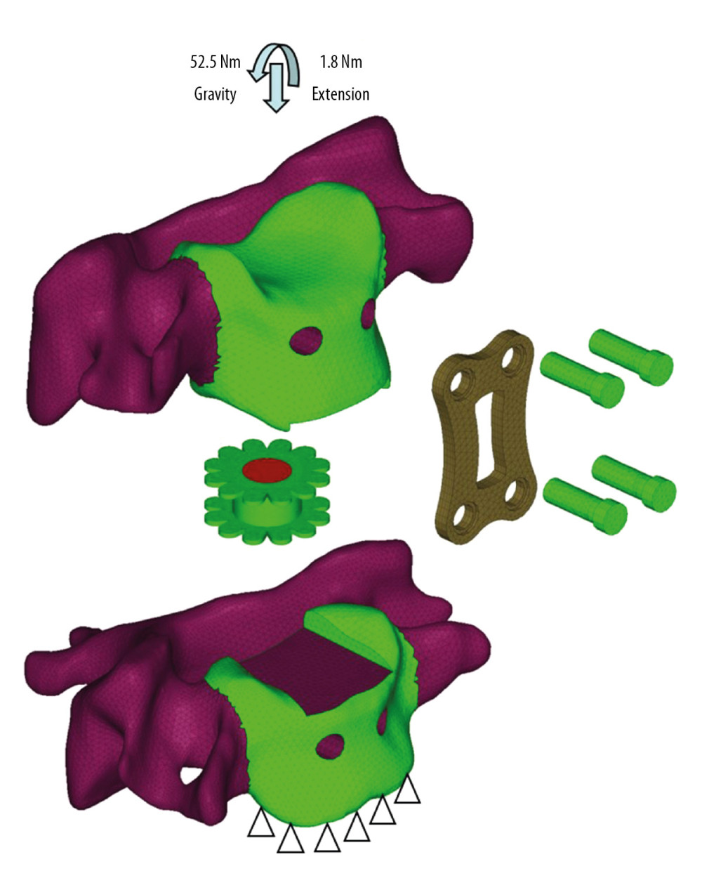 Figure 1. The C5–C6 FE model with cage implantation and its boundary and loading condition. A uniform compression force of 52.5 N mimicking the gravity of head, and a moment of 1.8 Nm mimicking the flexion motion pattern was exerted on the vertebrae of C5, while the nodes at the bottom of C6 were completely constrained.
 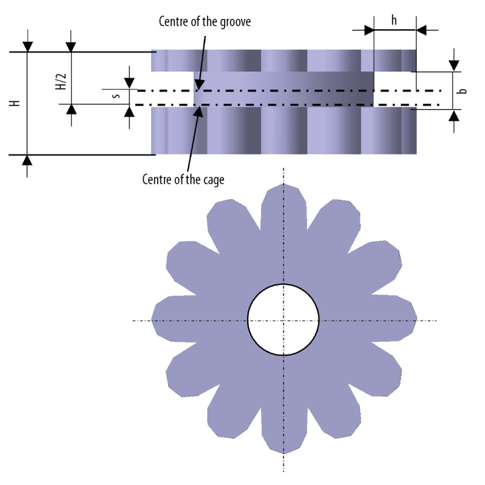 Figure 2. Schematic diagram of cervical cage’s structural dimensions. H – Distance from the superior and inferior edge; s – Distance between the center of cage and center of groove; h – Depth of the groove; b – Width of the groove.
 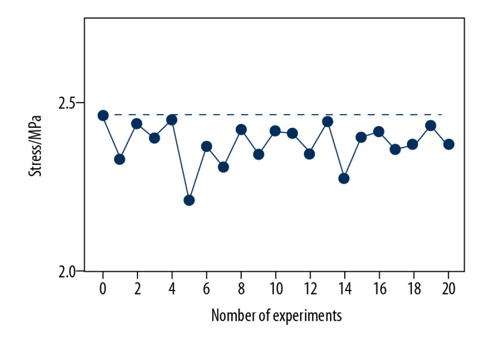 Figure 3. The comparison between Von Mises stresses of the original structural cage (the black dotted line) and bionic structural ones using quadratic rotation design (the blue polyline).
 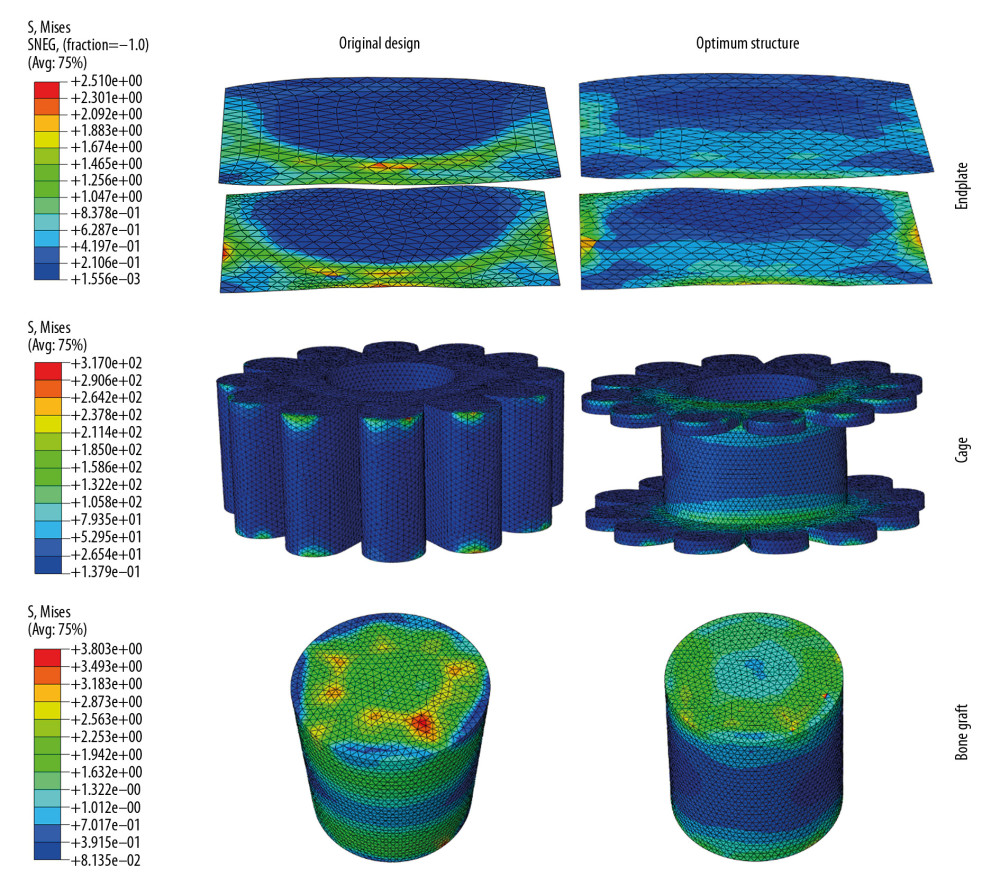 Figure 4. The stress distribution on endplates, cages, and bone grafts for original cage and optimum structural one.
 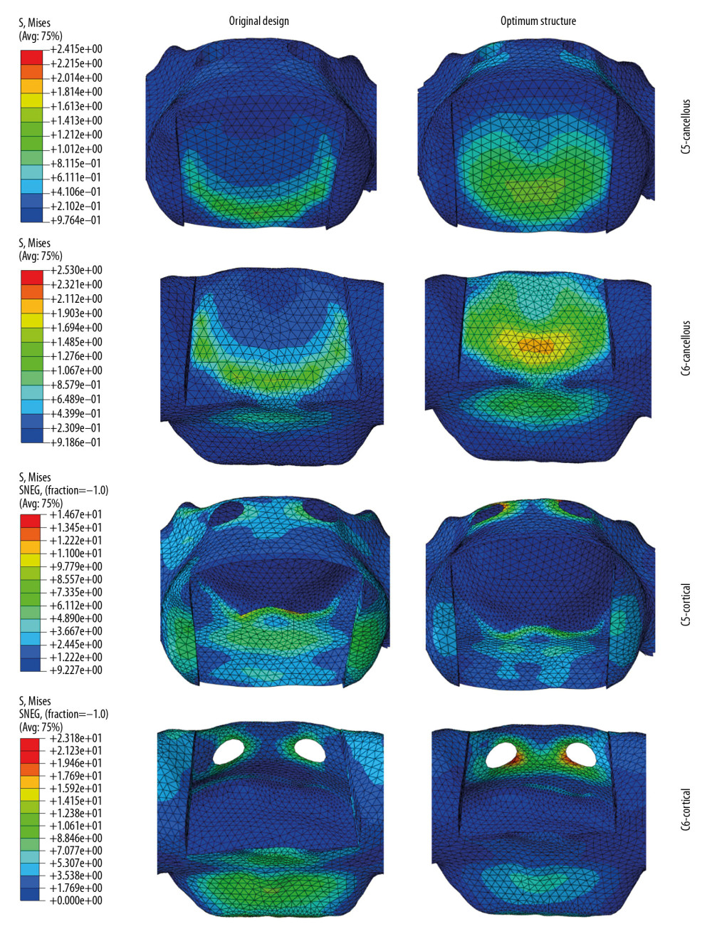 Figure 5. The stress distribution on cancellous and cortical bone of C5 and C6 for the original cage and optimum structural one.
 Tables
Table 1. The material properties [23–25] set in the C5–C6 FE model.![The material properties [23–25] set in the C5–C6 FE model.](https://jours.isi-science.com/imageXml.php?i=t1-medscimonit-26-e924236.jpg&idArt=924236&w=1000) Table 2. Factor level coding table.
Table 2. Factor level coding table.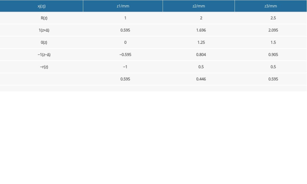 Table 3. Quadratic rotating experimental design scheme.
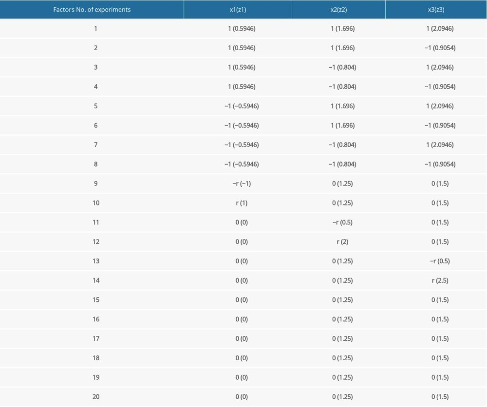 Table 4. The quadratic regression general rotation design parameter [21].
![The quadratic regression general rotation design parameter [21].](https://jours.isi-science.com/imageXml.php?i=t4-medscimonit-26-e924236.jpg&idArt=924236&w=1000) Table 5. The calculation results of regression coefficients.
Table 5. The calculation results of regression coefficients.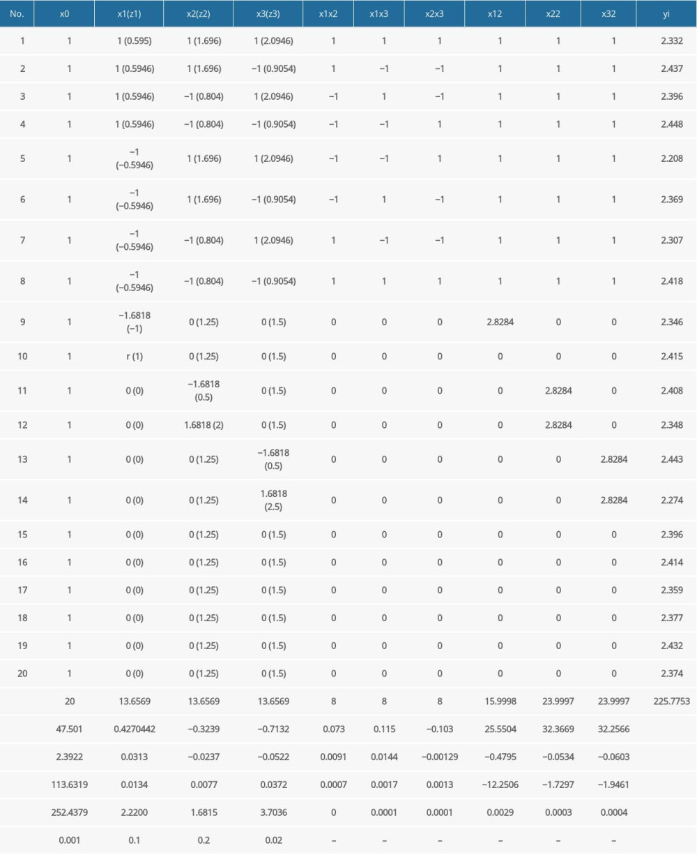
References
1. Liu C, Liu KX, Chu L, Posterior percutaneous endoscopic cervical discectomy through lamina-hole approach for cervical intervertebral disc herniation: Int J Neurosci, 2019; 129; 627-34
2. Balasa A, Bielecki M, Prokopienko M, Kunert P, Lateral approach for recurrent unilateral cervical radiculopathy after anterior discectomy with fusion. Report of two cases: Videosurgery Miniinv, 2019; 14; 348-52
3. Eco LC, Brayton A, Whitehead WE, Jea A, Reconstruction of the anterior craniocervical junction using an expandable cage after resection of a C1 chordoma in a 5-year-old child: Case report: J Neurosurg-Pediatr, 2019; 24; 62-65
4. Alvi MA, Kurian SJ, Wahood W, Assessing the difference in clinical and radiologic outcomes between expandable cage and nonexpandable cage among patients undergoing minimally invasive transforaminal interbody fusion: A systematic review and meta-analysis: World Neurosurg, 2019; 127; 596-606.e1
5. Goz V, Buser Z, D’Oro A, Complications and risk factors using structural allograft versus synthetic cage: Analysis 17783 anterior cervical discectomy and fusions using a national registry: Global Spine J, 2019; 9; 388-92
6. Wilke HJ, Kettler A, Goetz C, Claes L: Spine, 2000; 25(21); 2762-70
7. Kandziora F, Pflugmacher R, Schäfer J, Biomechanical comparison of cervical spine interbody fusion cages: Spine, 2001; 26(17); 1850-57
8. Kandziora F, Schollmeier G, Scholz M, Influence of cage design on interbody fusion in a sheep cervical spine model: J Neurosurg, 2002; 96(3); 321-32
9. Kandziora F, Pflugmacher R, Scholz M, Bioabsorbable interbody cages in a sheep cervical spine fusion model: Spine, 2004; 29(17); 1845-55
10. Oliver JD, Goncalves S, Kerezoudis P, Comparison of outcomes for anterior cervical discectomy and fusion with and without anterior plate fixation: A systematic review and meta-analysis: Spine, 2018; 43(7); E413-22
11. Fernandez-Fairen M, Alvarado E, Torres A, Eleven-year follow-up of two cohorts of patients comparing stand-alone porous tantalum cage versus autologous bone graft and plating in anterior cervical fusions: World Neurosurg, 2019; 122; E156-67
12. Noordhoek I, Koning MT, Vleggeert-Lankamp CLA, Evaluation of bony fusion after anterior cervical discectomy: A systematic literature review: Eur Spine J, 2019; 28(2); 386-99
13. Kettler A, Wilke HJ, Claes L: J Neurosurg, 2001; 94(1 Suppl); 97-107
14. Lu T, Liang H, Liu C, Effects of titanium mesh cage end structures on the compressive load at the endplate interface: A cadaveric biomechanical study: Med Sci Monit, 2017; 23; 2863-70
15. Mao CY, Ma YH, Wu SY, Wear resistance and wet skid resistance of composite bionic tire tread compounds with pit structure: Mater Res Express, 2019; 6; 085331
16. Li KY, Yang XY, Xue C, Biomimetic human lung-on-a-chip for modeling disease investigation: Biomicrofluidics, 2019; 13(3); 031501
17. Wang M, Dong HF, Li X, Control and optimization of a bionic robotic fish through a combination of CPG model and PSO: Neurocomputing, 2019; 337; 144-52
18. Wang J, Du ZZ, He ZT, Wang JJ, Exploring vibration transmission rule of an artificial spider web for potential application in invulnerability of wireless sensor network: Appl Bionics Biomech, 2019; 2019 5125034
19. Mohanty S, Dahia CL, Defects in intervertebral disc and spine during development, degeneration, and pain: New research directions for disc regeneration and therapy: Wires Dev Biol, 2019; 8(4); e343
20. Zhao RZ, Liu WQ, Xia TT, Yang L, Disordered mechanical stress and tissue engineering therapies in intervertebral disc degeneration: Polymers, 2019; 11(7); 1151
21. Kuo RF, Fang KM, Wong TY, Hu CY, Quantification of dental prostheses on cone-beam CT images by the Taguchi method: J Appl Clin Med Phys, 2016; 17; 207-20
22. Usma-Alvarez CC, Fuss FK, Subic A, User-centered design customization of rugby wheelchairs based on the Taguchi method: J Mech Design, 2014; 136(4); 041001
23. Fan CY, Chao CK, Hsu CC, Chao KH, The optimum cage position and orientation on the ALIF with facet screw fixation: A finite element analysis and the Taguchi method: J Mech, 2011; 27(3); 309-20
24. Yang K, Teo EC, Fuss FK, Application of Taguchi method in optimization of cervical ring cage: J Biomech, 2007; 40; 3251-56
25. Ren LQ, 2009, Beijing (NY), Science Press [in Chinese]
26. Wang J, Qian Z, Ren L, Biomechanical comparison of optimal shapes for the cervical intervertebral fusion cage for C5–C6 cervical fusion using the Anterior Cervical Plate and Cage (ACPC) fixation system: A finite element analysis: Med Sci Monit, 2019; 25; 8379-88
27. Zhang QH, Teo EC, Ng HW, Lee VS, Finite element analysis of moment-rotation relationships for human cervical spine: J Biomech, 2006; 39; 189-93
28. Ha SK, Finite element modeling of multi-level cervical spinal segments (C3–C6) and biomechanical analysis of an elastomer-type prosthetic disc: Med Eng Phys, 2006; 28; 534-41
29. Ng HW, Teo EC, Nonlinear finite-element analysis of the lower cervical spine (C4–C6) under axial loading: J Spinal Disord, 2001; 14; 201-10
30. Kallemeyn N, Gandhi A, Kode S, Validation of a C2–C7 cervical spine finite element model using specimen-specific flexibility data: Med Eng Phys, 2010; 32; 482-89
31. Panzer MB, Cronin DS, C4–C5 segment finite element model development, validation, and load-sharing investigation: J Biomech, 2009; 42; 480-90
32. Teo EC, Yang K, Fuss FK, Effects of cervical cages on load distribution of cancellous core-a finite element analysis: J Spinal Disord Tech, 2004; 17(3); 226-31
33. Natarajan RN, Chen BH, An HS, Andersson GBJ, Anterior cervical fusion: A finite element model study on motion segment stability including the effect of osteoporosis: Spine, 2000; 25(8); 955-61
34. Reilly DT, Burstein AH, Frankel VH, The elastic modulus for bone: J Biomech, 1974; 7; 271-75
35. Yang K, Teo EC, Fuss FK, Application of Taguchi method in optimization of cervical ring cage: J Biomech, 2007; 40; 3251-56
36. Meng L, Zhang Y, Lu Y, Three-dimensional finite element analysis of miniexternal fixation and Kirschner wire internal fixation in Bennett fracture treatment: Orthop Traumatol Surg Res, 2013; 99(1); 21-29
Figures
 Figure 1. The C5–C6 FE model with cage implantation and its boundary and loading condition. A uniform compression force of 52.5 N mimicking the gravity of head, and a moment of 1.8 Nm mimicking the flexion motion pattern was exerted on the vertebrae of C5, while the nodes at the bottom of C6 were completely constrained.
 Figure 2. Schematic diagram of cervical cage’s structural dimensions. H – Distance from the superior and inferior edge; s – Distance between the center of cage and center of groove; h – Depth of the groove; b – Width of the groove.
 Figure 3. The comparison between Von Mises stresses of the original structural cage (the black dotted line) and bionic structural ones using quadratic rotation design (the blue polyline).
 Figure 4. The stress distribution on endplates, cages, and bone grafts for original cage and optimum structural one.
 Figure 5. The stress distribution on cancellous and cortical bone of C5 and C6 for the original cage and optimum structural one.
 Tables
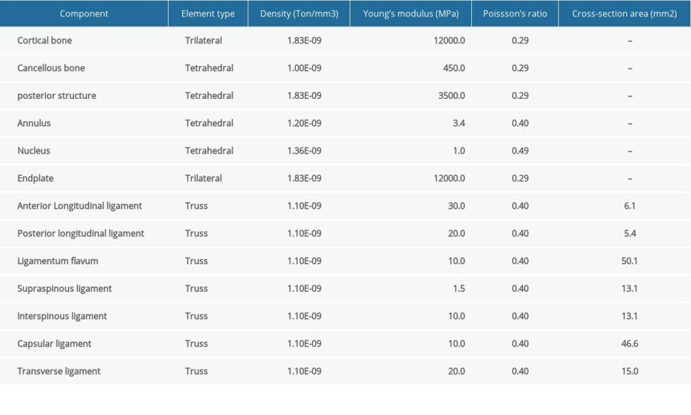 Table 1. The material properties [23–25] set in the C5–C6 FE model.
 Table 2. Factor level coding table.
 Table 3. Quadratic rotating experimental design scheme.
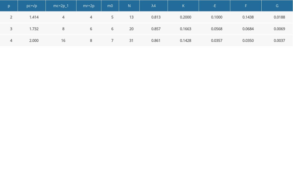 Table 4. The quadratic regression general rotation design parameter [21].
 Table 5. The calculation results of regression coefficients.
 Table 1. The material properties [23–25] set in the C5–C6 FE model.
 Table 2. Factor level coding table.
 Table 3. Quadratic rotating experimental design scheme.
 Table 4. The quadratic regression general rotation design parameter [21].
 Table 5. The calculation results of regression coefficients.
 In Press
07 Mar 2024 : Clinical Research
Knowledge of and Attitudes Toward Clinical Trials: A Questionnaire-Based Study of 179 Male Third- and Fourt...Med Sci Monit In Press; DOI: 10.12659/MSM.943468
08 Mar 2024 : Animal Research
Modification of Experimental Model of Necrotizing Enterocolitis (NEC) in Rat Pups by Single Exposure to Hyp...Med Sci Monit In Press; DOI: 10.12659/MSM.943443
18 Apr 2024 : Clinical Research
Comparative Analysis of Open and Closed Sphincterotomy for the Treatment of Chronic Anal Fissure: Safety an...Med Sci Monit In Press; DOI: 10.12659/MSM.944127
08 Mar 2024 : Laboratory Research
Evaluation of Retentive Strength of 50 Endodontically-Treated Single-Rooted Mandibular Second Premolars Res...Med Sci Monit In Press; DOI: 10.12659/MSM.944110
Most Viewed Current Articles
17 Jan 2024 : Review article
Vaccination Guidelines for Pregnant Women: Addressing COVID-19 and the Omicron VariantDOI :10.12659/MSM.942799
Med Sci Monit 2024; 30:e942799
14 Dec 2022 : Clinical Research
Prevalence and Variability of Allergen-Specific Immunoglobulin E in Patients with Elevated Tryptase LevelsDOI :10.12659/MSM.937990
Med Sci Monit 2022; 28:e937990
16 May 2023 : Clinical Research
Electrophysiological Testing for an Auditory Processing Disorder and Reading Performance in 54 School Stude...DOI :10.12659/MSM.940387
Med Sci Monit 2023; 29:e940387
01 Jan 2022 : Editorial
Editorial: Current Status of Oral Antiviral Drug Treatments for SARS-CoV-2 Infection in Non-Hospitalized Pa...DOI :10.12659/MSM.935952
Med Sci Monit 2022; 28:e935952


